How to Draw a Piping & Instrumentation (P&ID) Diagram
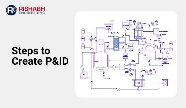
In the field of engineering, Piping and Instrumentation Diagrams (P&ID) are indispensable blueprints that offer a visual representation of the intricate processes within industrial settings. Proficiency in P&ID creation is essential for engineers across disciplines. This blog explores the essentials of how to draw a P&ID diagram, the steps, and the best approaches.
Components of a P&ID:
- Equipment Symbols: Representing various process equipment such as vessels, pumps, compressors, heat exchangers, etc.
- Control Systems: Illustrating the control loops, interlocks, and safety systems that regulate piping parameters.

- Piping and Instrumentation: Depicting the routing of piping systems, including valves, fittings, and instrumentation such as sensors, transmitters, and control valves.
- Annotations and Legends: For clarity, provide additional information such as equipment specifications, operating conditions, and symbols legends.
How Do You Draw A Piping And Instrumentation Diagram?
Rishabh Engineering offers technical solutions, mainly Piping and Instrumentation Diagrams. The company has become a trustworthy partner for organizations globally, offering complete services adapted to each project’s specific needs. The specialist team enables the establishment and optimization of P&IDs. It explores how we can seamlessly combine cutting-edge technology and industry standards to produce solutions that improve efficiency, safety, and production across numerous industries.
Listed below are some of the critical step-by-step guide on how to create P&IDs:
- Gather Relevant Information: Collect all necessary information, including process flow diagrams (PFDs), equipment specifications, instrumentation details, piping layouts, and control narratives. Understanding the process requirements and system components is essential for creating accurate P&IDs.
- Define Symbols and Standards: Familiarize yourself with industry-standard symbols and conventions used in diagrams. These symbols represent various equipment, valves, instruments, and control elements. Adhering to recognized standards such as ANSI/ISA-5.1 and ISO 10628 ensures consistency and clarity in P&ID documentation.
- Identify Equipment and Components: Begin by identifying and placing equipment such as pumps, vessels, heat exchangers, and tanks. Use standardized symbols to represent each equipment type, ensuring clear communication and easy interpretation by stakeholders.
- Establish Piping Connections: Connect equipment using appropriate piping lines to depict the flow of fluids or gases within the system. Indicate pipe sizes, materials, and specifications to represent the piping network accurately. Include fittings, valves, and control devices along the piping routes per the process requirements.
- Incorporate Instrumentation and Controls: Integrate instrumentation devices such as sensors, transmitters, controllers, and indicators into the P&ID. Clearly label each instrument and indicate its function, measurement parameters, and control signals. Use symbol legends or tables to provide detailed information about instrumentation tags and their corresponding descriptions.
- Define Control Systems and Logic: Depict control loops, interlocks, alarms, and safety systems within the P&ID to illustrate the control logic and operational sequences. Show the relationship between process variables, controllers, and final control elements to ensure effective process control and safety.
- Add Annotations and Text: Include descriptive text, labels, and annotations to provide additional information or clarify specific details. Use standardized fonts and text sizes for consistency and readability. Label equipment, instruments, piping, and control elements with relevant tags, identifiers, and specifications.
- Review and Verify: Conduct thorough reviews of the P&ID to validate accuracy, completeness, and compliance with design specifications in line with regulatory requirements. Engage stakeholders, subject matter experts, and project teams to identify discrepancies or inconsistencies in the review process.
- Update and Revise: Iterate on the design as needed based on feedback, revisions, or changes in project requirements. Maintain version control and document revision history to track updates and ensure traceability throughout the design lifecycle.
- Finalize and Publish: Once approved and finalized, prepare the document for distribution and use in the engineering, construction, and operational phases of the project. Publish the P&ID in digital and/or printed formats, making it accessible to relevant stakeholders and personnel involved in the project.
Piping & Instrumentation Diagram represent different parts and instruments using a consistent set of symbols. It is vital to understand these symbols to read the diagrams correctly. Read this blog to learn about typical P&ID symbols.
Software Tools for Creating P&IDs
Multiple software packages are available to assist you in generating, amending, and managing the said diagrams. It would include AutoCAD P&ID, SmartPlant P&ID, and Autodesk Plant 3D. These tools include user-friendly interfaces, extensive symbol libraries, and advanced features for developing and documenting complicated industrial processes.
Rishabh Engineering Recommended Best Practices for Creating P&ID
- Standardization: To ensure consistency and interoperability, adhere to industry standards such as ANSI/ISA-5.1-2009 (Instrumentation Symbols and Identification) and ISO 10628 (Flow Diagrams for Process Plants).
- Simplicity and Clarity: Strive for simplicity and clarity in design, avoiding clutter and unnecessary complexity to enhance readability and comprehension.
- Hierarchy and Organization: Organize the P&ID hierarchically, with major equipment and process streams depicted prominently, followed by detailed instrumentation and control systems.
- Color Coding: Utilize color coding to differentiate between process streams, equipment types, and safety-critical components, enhancing visual communication and quick comprehension.
- Version Control: Implement version control mechanisms to track revisions, updates, and approvals throughout the design lifecycle, ensuring document integrity and traceability.
- Training and Documentation: Provide training and documentation for personnel involved in creating, interpreting, and using P&IDs, fostering a culture of effective communication and collaboration.
Final Words
Creating accurate and detailed P&IDs is essential for effectively designing, operating, and maintaining industrial facilities. Any specialist engineering design company would leverage industry-standard symbols, conventions, and software tools. Further, you can work with a detailed engineering services company that can support you in developing comprehensive diagrams that facilitate clear communication, decision-making, and troubleshooting across all stages of a project’s lifecycle.
Ready to Master P&ID Creation?
Dive-in to learn the specific steps and best practices for developing P&IDs to understand industrial blueprints.
Related Blogs
Related Blogs
Best Structural Engineering Software for Accurate Analysis
Finding tools that simplify and improve the accuracy of the…
Detailed Engineering Considerations for Project Success
Engineering projects today require meticulous planning and execution across various…


